Er Diagram For Online Shopping For Admin
Knowledge
ER Diagrams for Online Shopping System
Know it All about ER Diagrams
If you're familiar with databases, you will probably know what an ER diagram is. But, for those who are new to this term, ER diagrams stand for Entity Relationship Diagram. These diagrams help us analyse the database by identifying relationships between entities, attributes, and critical information.
ER Diagram Examples for Online Shopping Systems
Now that you understand what an ER diagram is. You might be thinking, how is it related to Information systems? ER diagrams are handy in mapping out the functions the software will perform and how it will link different entities together.
For example, if you are making an online shopping system, you might have to look at the software from different perspectives. You need to consider the user interface, admin interface, how the products will be identified and the whole billing process. An ERD comes very handy here, where all entities are named and linked together to ensure the software caters to them all.
Using an ER diagram, you can resolve many problems during the planning phase of the information system rather than at the execution or testing phase. It allows you to map all the information in a graphical manner that is easy to understand and interpret.
Moreover, an ERD helps identify all the data that needs to be stored in the database. By linking entities, their attributes and their relationships, ERD helps determine all the requirements of an information system during its initial phase.
Entity Relationship diagrams are very useful in creating an online shopping system. Here are a few examples of taking inspiration from:
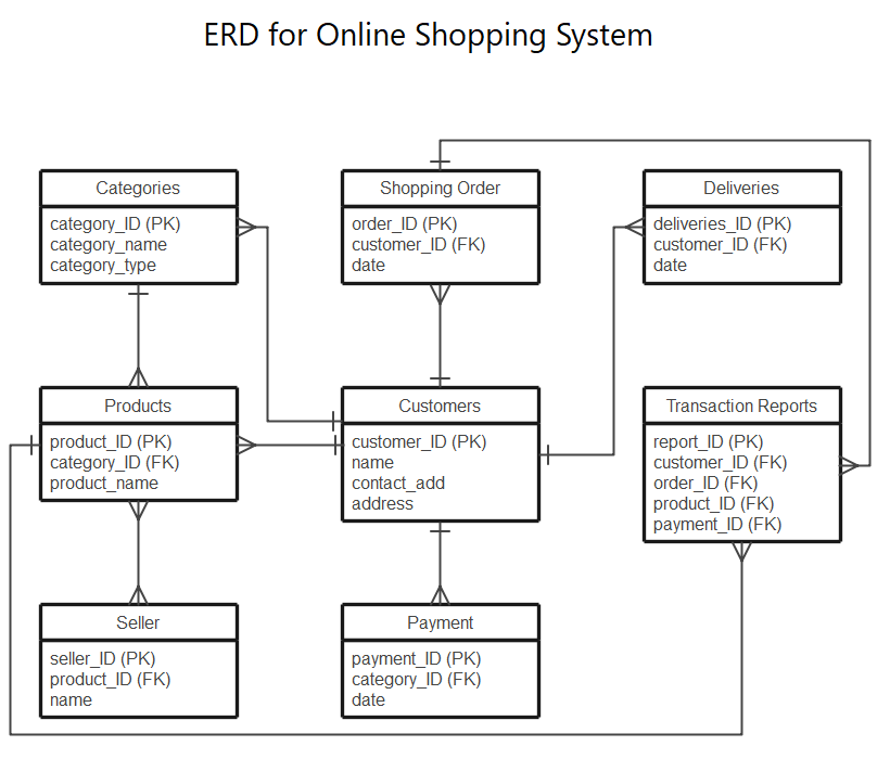
Example 1
This online shopping ERD maps out in detail all the critical entities, their attributes and relationships. It gives the rough details of all the entities involved, from browsing to payment. Creating an ERD for a shopping system can be beneficial to ensure that all the important aspects are a part of your system.
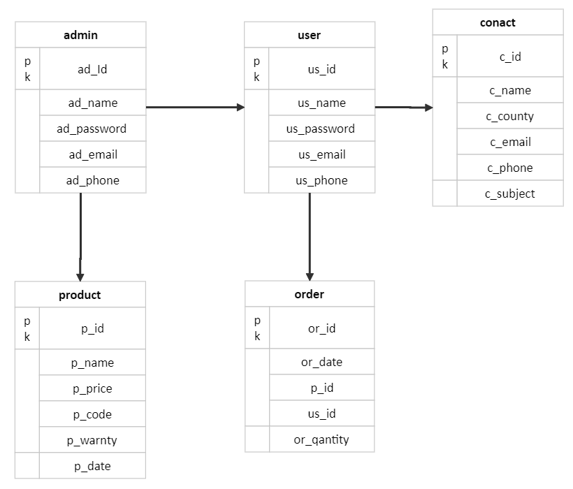
Example 2
Here's a small ER diagram for online shopping that shows all the entities like customer, admin, order and product. The ER diagram mentions all their attributes and the relationships between them. This is an excellent way to manage your database especially if your orders are in a large quantity.
Example 3
This ERD helps you look for data patterns in your database. If your shopping database is quite large, an ERD like this one will help you track customers, their orders and deliveries. You can track the purchase history of a customer or an item in an inventory through this graphical representation of your data.
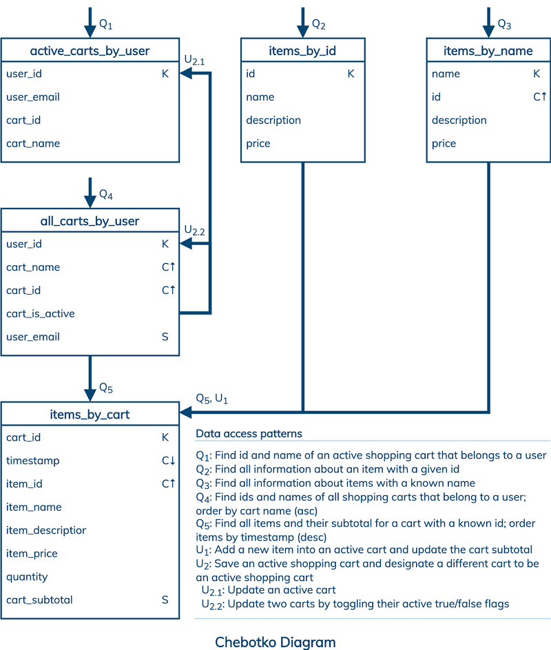
Image Source: www.datastax.com
Problems for Building an Online Shopping System
While designing an online shopping system database, you can encounter multiple problems. One of the significant problems in developing the shopping system is keeping in mind all the constraints. These constraints should ensure a customer can easily log in and purchase items by paying the listed price. To understand this better, let's look at the possible limitations while designing an Online Shopping System:
- The system allows multiple customers to log in and browse the products.
- Each product in the online shop has a unique ID or code.
- Customers can purchase products from multiple sections and add them to their carts.
- Customers can pay for their purchases through debit/ credit cards or cash.
- The system should keep track of each item with its unique code, price and product name.
- The system can track each customer and record their phone number, address and payment information.
- The staff using the software should be able to download the customer's information and shipments along with payment receipts.
- The customer should be able to track their order through the unique shipment code. They should be able to see and download their receipts.
- The customers should be able to contact support in case of any delays or problems.
Make sure your ERD can overcome all these constraints and is helpful in creating a system that is efficient and smart.
EdrawMax
All-in-One Diagram Software
Create more than 280 types of diagrams effortlessly
Start diagramming with various templates and symbols easily
- Superior file compatibility: Import and export drawings to various file formats, such as Visio
- Cross-platform supported (Windows, Mac, Linux, Web)
How to Create an ERD for Online Shopping System
Now let's follow a detailed strategy to help you build an online shopping system Step by Step.
Step 1: Identify all the entity sets related to your database. The entity sets for an online shopping system are:
- Website or Mobile Application
- Customer
- Admin
- Product
- Login/ Registration
- Shopping Cart
First of all, you need to start with the Mobile Application or website. This shows that the system is based on the software, and the main bridge between the customer and the store is the website or application.
Step 2: Now, you need to assign attributes to each of these entities like those given below:
- Website/ Mobile Application
- Customer
- Admin
- Product
- Login/ Registration
- Shopping Cart
Attributes: Domain Name, App Name
Attributes: Email, User ID, Password, Mobile Number, Customer ID, Country Name, District, Address, Postal Code etc.
Attributes: Admin ID, Admin Name, Password
Attributes: Product code, Product name, Product category, product price, product availability.
Attributes: User ID, Username, Password, forgot password, sign up
Attributes: Product ID, Product name, Total Price, Billing products.
Consider the rest of the entities like customers and products. The customers will need to register and log in first in order to purchase items. They can select the products online and put them in the shopping cart. The shopping cart will identify the product and its price immediately. An admin needs to be on the other end, ensuring the transaction goes smooth and there are no possible bugs. The admin can also offer support when needed and add new products or remove any old ones.
Step 3: Identify the key attributes. The key attribute is one specific attribute that uniquely identifies one entity from another in an entity set.
The key attribute for each of these will be:
- Product: Product ID
- Customer: Customer ID
- Admin: Admin ID
- Website or Mobile App: Domain name
- Shopping Cart: Product ID
- Log in / Registration: Username
Step 4: Create an ER diagram. In order to create an information system, you will need to map out the ER diagram first and then follow the steps using Java or SQL. This is how you can easily create an Entity Relationship diagram by identifying the entities and then connecting them to create a whole diagram.
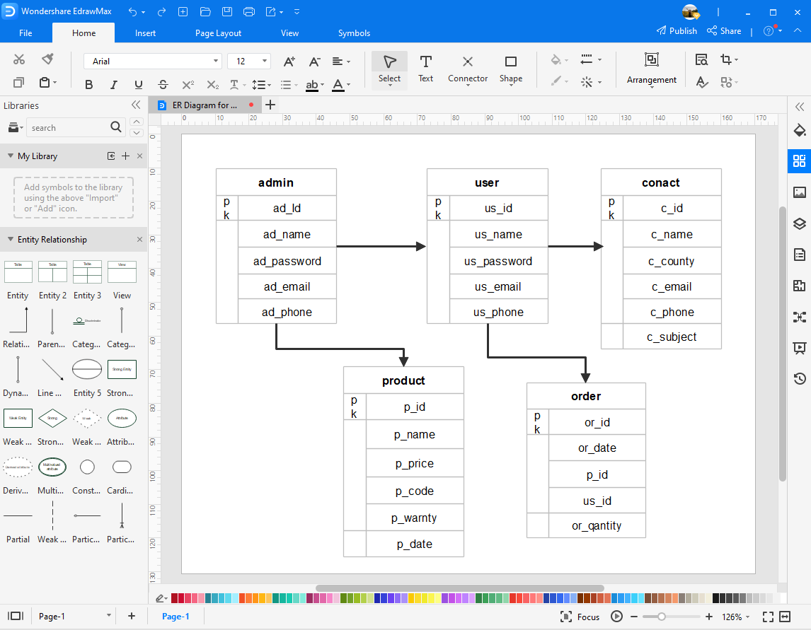
Use EdrawMax for ER Diagram Creation
It is imperative to use efficient diagramming tools for creating ER Diagrams for online shopping. Using the right tools will help you create diagrams that are more effective in serving their purpose. With the correct styles, formatting and tools, you can make your charts simpler and easier to understand. You might want to use the standard tools for more complex ER diagrams, but for complex diagrams, it is better to use professional tools.
EdrawMax is one such tool that has an excellent range of diagrams you can create. With an array of templates, you only need to modify the template if you are short on time. It is software for professionals and amateurs alike. Skilled professionals can choose to create their designs and diagrams using the gamut of tools and symbols available. With an interface similar to that of MS Suite, the software is highly user-friendly and easy to navigate. You can create better-looking and efficient diagrams using EdrawMax.
Related Articles
Source: https://www.edrawsoft.com/article/er-diagrams-for-online-shopping-system.html
Posted by: carmenrokickie0275631a.blogspot.com
Sub Entity In Er Diagram
Model or diagram describing interrelated things
An entity–relationship model (or ER model) describes interrelated things of interest in a specific domain of knowledge. A basic ER model is composed of entity types (which classify the things of interest) and specifies relationships that can exist between entities (instances of those entity types).

An entity–attribute-relationship diagram for a MMORPG using Chen's notation.
In software engineering, an ER model is commonly formed to represent things a business needs to remember in order to perform business processes. Consequently, the ER model becomes an abstract data model, that defines a data or information structure which can be implemented in a database, typically a relational database.
Entity–relationship modeling was developed for database and design by Peter Chen and published in a 1976 paper,[1] with variants of the idea existing previously.[2] Some ER models show super and subtype entities connected by generalization-specialization relationships,[3] and an ER model can be used also in the specification of domain-specific ontologies.
Introduction [edit]
An E-R model is usually the result of systematic analysis to define and describe what is important to processes in an area of a business. It does not define the business processes; it only presents a business data schema in graphical form. It is usually drawn in a graphical form as boxes (entities) that are connected by lines (relationships) which express the associations and dependencies between entities. An ER model can also be expressed in a verbal form, for example: one building may be divided into zero or more apartments, but one apartment can only be located in one building.
Entities may be characterized not only by relationships, but also by additional properties (attributes), which include identifiers called "primary keys". Diagrams created to represent attributes as well as entities and relationships may be called entity-attribute-relationship diagrams, rather than entity–relationship models.
An ER model is typically implemented as a database. In a simple relational database implementation, each row of a table represents one instance of an entity type, and each field in a table represents an attribute type. In a relational database a relationship between entities is implemented by storing the primary key of one entity as a pointer or "foreign key" in the table of another entity.
There is a tradition for ER/data models to be built at two or three levels of abstraction. Note that the conceptual-logical-physical hierarchy below is used in other kinds of specification, and is different from the three schema approach to software engineering.
- Conceptual data model
- This is the highest level ER model in that it contains the least granular detail but establishes the overall scope of what is to be included within the model set. The conceptual ER model normally defines master reference data entities that are commonly used by the organization. Developing an enterprise-wide conceptual ER model is useful to support documenting the data architecture for an organization.
- A conceptual ER model may be used as the foundation for one or more logical data models (see below). The purpose of the conceptual ER model is then to establish structural metadata commonality for the master data entities between the set of logical ER models. The conceptual data model may be used to form commonality relationships between ER models as a basis for data model integration.
- Logical data model
- A logical ER model does not require a conceptual ER model, especially if the scope of the logical ER model includes only the development of a distinct information system. The logical ER model contains more detail than the conceptual ER model. In addition to master data entities, operational and transactional data entities are now defined. The details of each data entity are developed and the relationships between these data entities are established. The logical ER model is however developed independently of the specific database management system into which it can be implemented.
- Physical data model
- One or more physical ER models may be developed from each logical ER model. The physical ER model is normally developed to be instantiated as a database. Therefore, each physical ER model must contain enough detail to produce a database and each physical ER model is technology dependent since each database management system is somewhat different.
- The physical model is normally instantiated in the structural metadata of a database management system as relational database objects such as database tables, database indexes such as unique key indexes, and database constraints such as a foreign key constraint or a commonality constraint. The ER model is also normally used to design modifications to the relational database objects and to maintain the structural metadata of the database.
The first stage of information system design uses these models during the requirements analysis to describe information needs or the type of information that is to be stored in a database. The data modeling technique can be used to describe any ontology (i.e. an overview and classifications of used terms and their relationships) for a certain area of interest. In the case of the design of an information system that is based on a database, the conceptual data model is, at a later stage (usually called logical design), mapped to a logical data model, such as the relational model; this in turn is mapped to a physical model during physical design. Note that sometimes, both of these phases are referred to as "physical design."
Entity–relationship model [edit]
Two related entities
![]()
An entity with an attribute

A relationship with an attribute
![]()
An entity may be defined as a thing capable of an independent existence that can be uniquely identified. An entity is an abstraction from the complexities of a domain. When we speak of an entity, we normally speak of some aspect of the real world that can be distinguished from other aspects of the real world.[4]
An entity is a thing that exists either physically or logically. An entity may be a physical object such as a house or a car (they exist physically), an event such as a house sale or a car service, or a concept such as a customer transaction or order (they exist logically—as a concept). Although the term entity is the one most commonly used, following Chen we should really distinguish between an entity and an entity-type. An entity-type is a category. An entity, strictly speaking, is an instance of a given entity-type. There are usually many instances of an entity-type. Because the term entity-type is somewhat cumbersome, most people tend to use the term entity as a synonym for this term
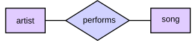
Entities can be thought of as nouns. Examples: a computer, an employee, a song, a mathematical theorem, etc.
A relationship captures how entities are related to one another. Relationships can be thought of as verbs, linking two or more nouns. Examples: an owns relationship between a company and a computer, a supervises relationship between an employee and a department, a performs relationship between an artist and a song, a proves relationship between a mathematician and a conjecture, etc.
The model's linguistic aspect described above is utilized in the declarative database query language ERROL, which mimics natural language constructs. ERROL's semantics and implementation are based on reshaped relational algebra (RRA), a relational algebra that is adapted to the entity–relationship model and captures its linguistic aspect.
Entities and relationships can both have attributes. Examples: an employee entity might have a Social Security Number (SSN) attribute, while a proved relationship may have a date attribute.
All entities except weak entities must have a minimal set of uniquely identifying attributes which may be used as a unique/primary key.
Entity–relationship diagrams don't show single entities or single instances of relations. Rather, they show entity sets (all entities of the same entity type) and relationship sets (all relationships of the same relationship type). Examples: a particular song is an entity; the collection of all songs in a database is an entity set; the eaten relationship between a child and his lunch is a single relationship; the set of all such child-lunch relationships in a database is a relationship set. In other words, a relationship set corresponds to a relation in mathematics, while a relationship corresponds to a member of the relation.
Certain cardinality constraints on relationship sets may be indicated as well.
Mapping natural language [edit]
Chen proposed the following "rules of thumb" for mapping natural language descriptions into ER diagrams: "English, Chinese and ER diagrams" by Peter Chen.
| English grammar structure | ER structure |
|---|---|
| Common noun | Entity type |
| Proper noun | Entity |
| Transitive verb | Relationship type |
| Intransitive verb | Attribute type |
| Adjective | Attribute for entity |
| Adverb | Attribute for relationship |
Physical view show how data is actually stored.
Relationships, roles and cardinalities [edit]
In Chen's original paper he gives an example of a relationship and its roles. He describes a relationship "marriage" and its two roles "husband" and "wife".
A person plays the role of husband in a marriage (relationship) and another person plays the role of wife in the (same) marriage. These words are nouns. That is no surprise; naming things requires a noun.
Chen's terminology has also been applied to earlier ideas. The lines, arrows and crow's-feet of some diagrams owes more to the earlier Bachman diagrams than to Chen's relationship diagrams.
Another common extension to Chen's model is to "name" relationships and roles as verbs or phrases.
Role naming [edit]
It has also become prevalent to name roles with phrases such as is the owner of and is owned by. Correct nouns in this case are owner and possession. Thus person plays the role of owner and car plays the role of possession rather than person plays the role of, is the owner of, etc.
The use of nouns has direct benefit when generating physical implementations from semantic models. When a person has two relationships with car then it is possible to generate names such as owner_person and driver_person, which are immediately meaningful.[5]
Cardinalities [edit]
Modifications to the original specification can be beneficial. Chen described look-across cardinalities. As an aside, the Barker–Ellis notation, used in Oracle Designer, uses same-side for minimum cardinality (analogous to optionality) and role, but look-across for maximum cardinality (the crows foot).[ clarification needed ]
In Merise,[6] Elmasri & Navathe[7] and others[8] there is a preference for same-side for roles and both minimum and maximum cardinalities. Recent researchers (Feinerer,[9] Dullea et al.[10]) have shown that this is more coherent when applied to n-ary relationships of order greater than 2.
In Dullea et al. one reads "A 'look across' notation such as used in the UML does not effectively represent the semantics of participation constraints imposed on relationships where the degree is higher than binary."
In Feinerer it says "Problems arise if we operate under the look-across semantics as used for UML associations. Hartmann[11] investigates this situation and shows how and why different transformations fail." (Although the "reduction" mentioned is spurious as the two diagrams 3.4 and 3.5 are in fact the same) and also "As we will see on the next few pages, the look-across interpretation introduces several difficulties that prevent the extension of simple mechanisms from binary to n-ary associations."
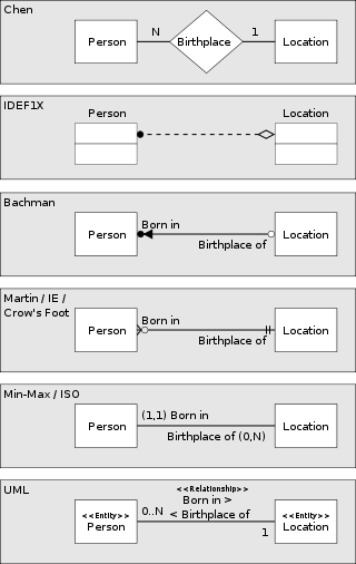
Various methods of representing the same one to many relationship. In each case, the diagram shows the relationship between a person and a place of birth: each person must have been born at one, and only one, location, but each location may have had zero or more people born at it.

Two related entities shown using Crow's Foot notation. In this example, an optional relationship is shown between Artist and Song; the symbols closest to the song entity represents "zero, one, or many", whereas a song has "one and only one" Artist. The former is therefore read as, an Artist (can) perform(s) "zero, one, or many" song(s).
Chen's notation for entity–relationship modeling uses rectangles to represent entity sets, and diamonds to represent relationships appropriate for first-class objects: they can have attributes and relationships of their own. If an entity set participates in a relationship set, they are connected with a line.
Attributes are drawn as ovals and are connected with a line to exactly one entity or relationship set.
Cardinality constraints are expressed as follows:
- a double line indicates a participation constraint, totality or surjectivity: all entities in the entity set must participate in at least one relationship in the relationship set;
- an arrow from entity set to relationship set indicates a key constraint, i.e. injectivity: each entity of the entity set can participate in at most one relationship in the relationship set;
- a thick line indicates both, i.e. bijectivity: each entity in the entity set is involved in exactly one relationship.
- an underlined name of an attribute indicates that it is a key: two different entities or relationships with this attribute always have different values for this attribute.
Attributes are often omitted as they can clutter up a diagram; other diagram techniques often list entity attributes within the rectangles drawn for entity sets.
Related diagramming convention techniques:
- Bachman notation
- Barker's notation
- EXPRESS
- IDEF1X
- § Crow's foot notation (also Martin notation)
- (min, max)-notation of Jean-Raymond Abrial in 1974
- UML class diagrams
- Merise
- Object-role modeling
Crow's foot notation [edit]
Crow's foot notation, the beginning of which dates back to an article by Gordon Everest (1976),[12] is used in Barker's notation, Structured Systems Analysis and Design Method (SSADM) and information technology engineering. Crow's foot diagrams represent entities as boxes, and relationships as lines between the boxes. Different shapes at the ends of these lines represent the relative cardinality of the relationship.
Crow's foot notation was used in the consultancy practice CACI. Many of the consultants at CACI (including Richard Barker) subsequently moved to Oracle UK, where they developed the early versions of Oracle's CASE tools, introducing the notation to a wider audience.
With this notation, relationships cannot have attributes. Where necessary, relationships are promoted to entities in their own right: for example, if it is necessary to capture where and when an artist performed a song, a new entity "performance" is introduced (with attributes reflecting the time and place), and the relationship of an artist to a song becomes an indirect relationship via the performance (artist-performs-performance, performance-features-song).
Three symbols are used to represent cardinality:
- the ring represents "zero"
- the dash represents "one"
- the crow's foot represents "many" or "infinite"
These symbols are used in pairs to represent the four types of cardinality that an entity may have in a relationship. The inner component of the notation represents the minimum, and the outer component represents the maximum.
- ring and dash → minimum zero, maximum one (optional)
- dash and dash → minimum one, maximum one (mandatory)
- ring and crow's foot → minimum zero, maximum many (optional)
- dash and crow's foot → minimum one, maximum many (mandatory)
Model usability issues [edit]
| | This section needs expansion with: fan trap causes. You can help by adding to it. (February 2018) |
In using a modeled database, users can encounter two well known issues where the returned results mean something other than the results assumed by the query author.
The first is the 'fan trap'. It occurs with a (master) table that links to multiple tables in a one-to-many relationship. The issue derives its name from the way the model looks when it's drawn in an entity–relationship diagram: the linked tables 'fan out' from the master table. This type of model looks similar to a star schema, a type of model used in data warehouses. When trying to calculate sums over aggregates using standard SQL over the master table, unexpected (and incorrect) results may occur. The solution is to either adjust the model or the SQL. This issue occurs mostly in databases for decision support systems, and software that queries such systems sometimes includes specific methods for handling this issue.
The second issue is a 'chasm trap'. A chasm trap occurs when a model suggests the existence of a relationship between entity types, but the pathway does not exist between certain entity occurrences. For example, a Building has one-or-more Rooms, that hold zero-or-more Computers. One would expect to be able to query the model to see all the Computers in the Building. However, Computers not currently assigned to a Room (because they are under repair or somewhere else) are not shown on the list. Another relation between Building and Computers is needed to capture all the computers in the building. This last modelling issue is the result of a failure to capture all the relationships that exist in the real world in the model. See Entity-Relationship Modelling 2 for details.
Entity–relationships and semantic modeling [edit]
Semantic model [edit]
A semantic model is a model of concepts, it is sometimes called a "platform independent model". It is an intensional model. At least since Carnap, it is well known that:[13]
- "...the full meaning of a concept is constituted by two aspects, its intension and its extension. The first part comprises the embedding of a concept in the world of concepts as a whole, i.e. the totality of all relations to other concepts. The second part establishes the referential meaning of the concept, i.e. its counterpart in the real or in a possible world".
Extension model [edit]
An extensional model is one that maps to the elements of a particular methodology or technology, and is thus a "platform specific model". The UML specification explicitly states that associations in class models are extensional and this is in fact self-evident by considering the extensive array of additional "adornments" provided by the specification over and above those provided by any of the prior candidate "semantic modelling languages"."UML as a Data Modeling Notation, Part 2"
Entity–relationship origins [edit]
Peter Chen, the father of ER modeling said in his seminal paper:
- "The entity-relationship model adopts the more natural view that the real world consists of entities and relationships. It incorporates some of the important semantic information about the real world." [1]
In his original 1976 article Chen explicitly contrasts entity–relationship diagrams with record modelling techniques:
- "The data structure diagram is a representation of the organization of records and is not an exact representation of entities and relationships."
Several other authors also support Chen's program:[14] [15] [16] [17] [18]
Philosophical alignment [edit]
Chen is in accord with philosophical traditions from the time of the Ancient Greek philosophers: Plato and Aristotle.[19] Plato himself associates knowledge with the apprehension of unchanging Forms (namely, archetypes or abstract representations of the many types of things, and properties) and their relationships to one another.
Limitations [edit]
- An ER model is primarily conceptual, an ontology that expresses predicates in a domain of knowledge.
- ER models are readily used to represent relational database structures (after Codd and Date) but not so often to represent other kinds of data structure (data warehouses, document stores etc.)
- Some ER model notations include symbols to show super-sub-type relationships and mutual exclusion between relationships; some don't.
- An ER model does not show an entity's life history (how its attributes and/or relationships change over time in response to events). For many systems, such state changes are nontrivial and important enough to warrant explicit specification.
- Some[ who? ] have extended ER modeling with constructs to represent state changes, an approach supported by the original author;[20] an example is Anchor Modeling.
- Others model state changes separately, using state transition diagrams or some other process modeling technique.
- Many other kinds of diagram are drawn to model other aspects of systems, including the 14 diagram types offered by UML.[21]
- Today, even where ER modeling could be useful, it is uncommon because many use tools that support similar kinds of model, notably class diagrams for OO programming and data models for relational database management systems. Some of these tools can generate code from diagrams and reverse-engineer diagrams from code.
- In a survey, Brodie and Liu[22] could not find a single instance of entity–relationship modeling inside a sample of ten Fortune 100 companies. Badia and Lemire[23] blame this lack of use on the lack of guidance but also on the lack of benefits, such as lack of support for data integration.
- The enhanced entity–relationship model (EER modeling) introduces several concepts not in ER modeling, but are closely related to object-oriented design, like is-a relationships.
- For modelling temporal databases, numerous ER extensions have been considered.[24] Similarly, the ER model was found unsuitable for multidimensional databases (used in OLAP applications); no dominant conceptual model has emerged in this field yet, although they generally revolve around the concept of OLAP cube (also known as data cube within the field).[25]
See also [edit]
- Associative entity
- Concept map
- Database design
- Data structure diagram
- Enhanced entity–relationship model
- Enterprise architecture framework
- Entity Data Model
- Value range structure diagrams
- Comparison of data modeling tools
- Ontology
- Object-role modeling
- Three schema approach
- Structured entity relationship model
- Schema-agnostic databases
References [edit]
- ^ a b Chen, Peter (March 1976). "The Entity-Relationship Model - Toward a Unified View of Data". ACM Transactions on Database Systems. 1 (1): 9–36. CiteSeerX10.1.1.523.6679. doi:10.1145/320434.320440. S2CID 52801746.
- ^ A.P.G. Brown, "Modelling a Real-World System and Designing a Schema to Represent It", in Douque and Nijssen (eds.), Data Base Description, North-Holland, 1975, ISBN 0-7204-2833-5.
- ^ "Lesson 5: Supertypes and Subtypes". docs.microsoft.com.
- ^ Beynon-Davies, Paul (2004). Database Systems. Basingstoke, UK: Palgrave: Houndmills. ISBN978-1403916013.
- ^ "The Pangrammaticon: Emotion and Society". January 3, 2013.
- ^ Hubert Tardieu, Arnold Rochfeld and René Colletti La methode MERISE: Principes et outils (Paperback - 1983)
- ^ Elmasri, Ramez, B. Shamkant, Navathe, Fundamentals of Database Systems, third ed., Addison-Wesley, Menlo Park, CA, USA, 2000.
- ^ ER 2004 : 23rd International Conference on Conceptual Modeling, Shanghai, China, November 8-12, 2004. 2004-10-27. ISBN9783540237235.
- ^ "A Formal Treatment of UML Class Diagrams as an Efficient Method for Configuration Management 2007" (PDF).
- ^ "James Dullea, Il-Yeol Song, Ioanna Lamprou - An analysis of structural validity in entity-relationship modeling 2002" (PDF).
- ^ Hartmann, Sven. "Reasoning about participation constraints and Chen's constraints Archived 2013-05-10 at the Wayback Machine". Proceedings of the 14th Australasian database conference-Volume 17. Australian Computer Society, Inc., 2003.
- ^ G. Everest, "BASIC DATA STRUCTURE MODELS EXPLAINED WITH A COMMON EXAMPLE", in Computing Systems 1976, Proceedings Fifth Texas Conference on Computing Systems, Austin,TX, 1976 October 18–19, pages 39-46. (Long Beach, CA: IEEE Computer Society Publications Office).
- ^ "The Role of Intensional and Extensional Interpretation in Semantic Representations".
- ^ Kent in "Data and Reality" :
- "One thing we ought to have clear in our minds at the outset of a modelling endeavour is whether we are intent on describing a portion of "reality" (some human enterprise) or a data processing activity."
- ^ Abrial in "Data Semantics" : "... the so called "logical" definition and manipulation of data are still influenced (sometimes unconsciously) by the "physical" storage and retrieval mechanisms currently available on computer systems."
- ^ Stamper: "They pretend to describe entity types, but the vocabulary is from data processing: fields, data items, values. Naming rules don't reflect the conventions we use for naming people and things; they reflect instead techniques for locating records in files."
- ^ In Jackson's words: "The developer begins by creating a model of the reality with which the system is concerned, the reality that furnishes its [the system's] subject matter ..."
- ^ Elmasri, Navathe: "The ER model concepts are designed to be closer to the user's perception of data and are not meant to describe the way in which data will be stored in the computer."
- ^ Paolo Rocchi, Janus-Faced Probability, Springer, 2014, p. 62.
- ^ P. Chen. Suggested research directions for a new frontier: Active conceptual modeling. ER 2006, volume 4215 of Lecture Notes in Computer Science, pages 1–4. Springer Berlin / Heidelberg, 2006.
- ^ Carte, Traci A.; Jasperson, Jon (Sean); and Cornelius, Mark E. (2020) "Integrating ERD and UML Concepts When Teaching Data Modeling," Journal of Information Systems Education: Vol. 17 : Iss. 1 , Article 9.
- ^ The power and limits of relational technology in the age of information ecosystems Archived 2016-09-17 at the Wayback Machine. On The Move Federated Conferences, 2010.
- ^ A. Badia and D. Lemire. A call to arms: revisiting database design. Citeseerx,
- ^ Gregersen, Heidi; Jensen, Christian S. (1999). "Temporal Entity-Relationship models—a survey". IEEE Transactions on Knowledge and Data Engineering. 11 (3): 464–497. CiteSeerX10.1.1.1.2497. doi:10.1109/69.774104.
- ^ RICCARDO TORLONE (2003). "Conceptual Multidimensional Models" (PDF). In Maurizio Rafanelli (ed.). Multidimensional Databases: Problems and Solutions. Idea Group Inc (IGI). ISBN978-1-59140-053-0.
Further reading [edit]
- Chen, Peter (2002). "Entity-Relationship Modeling: Historical Events, Future Trends, and Lessons Learned" (PDF). Software pioneers. Springer-Verlag. pp. 296–310. ISBN978-3-540-43081-0.
- Barker, Richard (1990). CASE Method: Entity Relationship Modelling. Addison-Wesley. ISBN978-0201416961.
- Barker, Richard (1990). CASE Method: Tasks and Deliverables. Addison-Wesley. ISBN978-0201416978.
- Mannila, Heikki; Räihä, Kari-Jouko (1992). The Design of Relational Databases. Addison-Wesley. ISBN978-0201565232.
- Thalheim, Bernhard (2000). Entity-Relationship Modeling: Foundations of Database Technology. Springer. ISBN978-3-540-65470-4.
- Bagui, Sikha; Earp, Richard (2011). Database Design Using Entity-Relationship Diagrams (2nd ed.). CRC Press. ISBN978-1-4398-6176-9.
External links [edit]
- "The Entity Relationship Model: Toward a Unified View of Data"
- Entity Relationship Modelling
- Logical Data Structures (LDSs) - Getting started by Tony Drewry.
- Crow's Foot Notation
- Kinds of Data Models -- and How to Name Them presentation by David Hay
Source: https://en.wikipedia.org/wiki/Entity%E2%80%93relationship_model
Posted by: carmenrokickie0275631a.blogspot.com
2017 Vw Tiguan Fuse Box Diagram
How to Replace a VW Vehicle Key

CCO/kaboompics/Pixabay
Misplacing your Volkswagen car key is frustrating enough, but what happens if you lose it permanently? You have no other option than to seek a replacement, but if you've never been in this position before, you may not have a clue how to get a new key. It turns out there are a few ways to do it.
Whether you're stranded somewhere or you lost your key at home, you need to get a VW key replacement as soon as possible. Here's a look at how to get a new key as soon as possible.
Write Down Your VIN Number
The first thing you need to do is jot down your vehicle's VIN number. Depending on the model of Volkswagen you own, the VIN may be in one of a few places. Most likely, it's located with the other VW dashboard symbols on the driver's side. It may also be on the door jam or on one of the rear wheels.
If you're having trouble locating it on the vehicle and your purchase documentation is long gone, you can find it on your insurance policy. The VIN is 17 characters long and consists of both letters and numbers. Make sure you write it down correctly, as this is an important detail when getting a new key from a locksmith.
Call a Locksmith
If you need quick access to your car and a new key right away, calling a locksmith is your best bet. Not only can a locksmith get into your vehicle, he or she can also help with a replacement key. If you own an older model Volkswagen, the locksmith will have to decode the locks in order to make a new key.
If you own a newer model, a locksmith can cut a new key based on a code for your car, and this requires your VIN number. Even if you have a key fob, getting a replacement from a locksmith is possible by allowing him or her to access the onboard computer for your vehicle. Make sure the locksmith has the ability to do this before hiring.
Get a New Key from Your Dealership
Another option is going to your Volkswagen dealership to get a new key. If you opt for this approach, you have to take a few things with you, including proof of ownership and your driver's license. Call in advance and ask if they require anything else.
Keep in mind your dealer has to order a replacement, so you won't have access to your vehicle right away. It may take two to three days. The dealer also needs the VIN number to place the order. Once the replacement arrives, they will have to program the computer so the replacement works if you have a newer model VW.
Understand the Cost
Unfortunately, getting a VW key replacement is going to cost you some money. If your car uses a fob, a replacement can be rather expensive. Expect to pay as much as $350. You may also have to factor in the cost of getting your car towed.
If you use a locksmith route, you have to pay for the service along with the key itself. Make sure you ask for a quote. Some locksmiths take advantage of people who are desperate and charge unreasonable amounts. However you get a new key, make sure to get a spare key made so this doesn't happen again.
Look for Keys Online
If you want to avoid paying hundreds of dollars for a new key, check for an online provider is an option. Many key dealers advertise their services on sites like eBay or Amazon. Keep in mind that replacing an older key is much easier. Some of these dealers can't handle newer keys or fobs.
However, with a little digging, you may be able to find someone who has the equipment and knowledge to make a new programmed key. If so, these sources may charge less than a locksmith or a dealership. Make sure you have the VIN and ask if they need any other VW engine specifications.
More From QuestionsAnswered.net
Source: https://www.questionsanswered.net/article/how-to-replace-a-vw-vehicle-key?utm_content=params%3Ao%3D740012%26ad%3DdirN%26qo%3DserpIndex
Posted by: carmenrokickie0275631a.blogspot.com
The Two Reconstructions The Struggle For Black Enfranchisement Download Pdf
Radical Reconstruction brought about revolutionary changes to the nature of democracy and the structure of American society, especially in the South. Centered on Part Four of Facing History's video series about Reconstruction, and enhanced with activities and readings, this lesson will help students explore the consequences of Radical Reconstruction. Students will reflect on how the ground-breaking changes that occurred because of the new laws in the late 1860s and early 1870s affected the strength of American democracy.
This lesson is part of Facing History's work on the Reconstruction era, and part of a series of video-based web lessons. Use this lesson to engage students in a conversation about the period of interracial democracy that occurred during Radical Reconstruction. In addition to the suggestions below, see Lesson 8 inThe Reconstruction Era and the Fragility of Democracy for more resources and background information.
- Reflect and Discuss
The video Interracial Democracy introduces students to the dramatic political and social changes that occurred in the South as a result of Radical Reconstruction. The video focuses specifically on black suffrage. Before showing the video, students should reflect on the revolutionary and unprecedented nature of granting political and civil rights to millions of people who two years prior were enslaved.
Ask students to write a short response to the following quotation by historian Eric Foner:
Never before in history had so large a group of emancipated slaves suddenly achieved political and civil rights. And the coming of black suffrage in the South in 1867 inspired a sense of millennial possibility second only to emancipation itself. Former slaves now stood on equal footing with whites, declared a speaker at a mass meeting in Savannah; before them lay "a field, too vast for contemplation."
In their responses, students might reflect on what effects they think black suffrage will have on the lives of individual freedpeople, the South, and the nation as a whole. After students have spent a few minutes recording their thoughts, use the Think, Pair, Share teaching strategy to help them discuss their ideas about these questions with each other.
- Watch
Show the video Interracial Democracy.Before showing the video, share the following questions with students to guide their note taking:
- What was Radical Reconstruction?
- What do you think the term "interracial democracy" means? Why do you think historians like Eric Foner have used this term to describe this history?
- About how many African Americans held political office during Reconstruction? What types of offices did they hold?
- In what ways did blacks and whites work together in the South during Reconstruction? What obstacles got in the way of such cooperation?
-
What were some of the policies and accomplishments of interracial state governments during Reconstruction? Who benefited from these policies and accomplishments? Who opposed them?
- Read and Analyze
Build on what students learned from the video by having them read and analyze the following documents exploring interracial democracy in the 1860's and 1870's:

Reading
Race in US History
The Role of Carpetbaggers
Alexander White, a white congressman from Alabama, describes the role that "carpetbaggers" and "scalawags" played in Reconstruction politics.

Reading
Race in US History
Reconstructing Mississippi
Learn about the accomplishments of the first interracial legislature in Mississippi from the account of John Roy Lynch, a freedman who served in the state's House of Representatives.

Reading
Race in US History
Improving Education in South Carolina
Samuel J. Lee, elected to the South Carolina House of Representatives in 1868, describes improvements to the state education system made during Reconstruction.
The Gallery Walk teaching strategy can provide a simple structure for students to move around the room, read, and discuss documents from this collection.
After students have read and discussed several, if not all, of the documents, give them notecards and ask them to write newspaper headlines on the cards that capture how Radical Reconstruction laws and amendments changed the country. Explain that a good headline usually summarizes an idea or event in 12 words or fewer. Alternatively, you might have students compose a tweet (which is 140 characters or fewer).
Below their headlines or tweets, have students list three pieces of evidence they recorded from the documents they analyzed or from the video they watched that support or explain their headline or tweet.
Finally, consider asking students to rethink their headlines from the perspectives of either Radical Republicans or Southern Democrats. How might their headlines be different from each of these points of view?
Source: https://www.facinghistory.org/reconstruction-era/lessons/interracial-democracy
Posted by: carmenrokickie0275631a.blogspot.com
The Aubin Academy Revit Architecture 2016 And Beyond Pdf Download

This past week I received my copy of the 2016 version of the "Master Autodesk Revit Architecture" series paperback book in the mail. While this was not something new to me, as I've been "collecting" them since the 2009 version, this one is special. Why you ask, well because this copy came direct to me from one of the authors, Eddy Krygiel …….and it was signed!

It was back in 2008 when I was just learning Revit that I pickup my first copy of a Revit book by Eddy, Introducing Revit Architecture 2009 – BIM for Beginners.

This very quickly lead me to move on to the Mastering Series and I purchased the Master Revit Architecture 2009 book.

And from there on I've been hooked and have got the new version of Mastering Revit Architecture every year when it comes out. In fact this year, thanks to Eddy's generous gift, I got 2 copies, the paper back for my collection as well as the digital version (Kindle) for the first time. The digital version (e-book) is very handy because know I have a reference with me at all times, wherever I am, on my phone (Android), iPad, or laptop.
Now I must confess, aside from that first Induction book I have not read any of these books cover to cover. I do however use them as a reference on a regular basis as well as one of many way to see what's new with Revit every year. I also enjoy the exercises and data sets that are included with the books each year (can be downloaded from a website link that is given in the books).
The Books themselves are very well written, and even though they are large (normally over 1000 pages) they are not dry like a text book. They are put together in a way that makes sense to the user and are full of practical examples from the real world. There is also this great little section at the end of each chapter called "The Bottom Line". This is where they give you a quick recap of what you learned in the chapter as well as key area's of the chapter that you should master. These are in the form of a "Master It" question after each topic they recap within "The Bottom Line" section.
I know there are may great reference books and websites out there for learning Revit Architecture, but for my money this series is the one I come back to every year!
If you are interested in checking out the 2016 version of Mastering Revit Architecture you can do so at the links below:
Mastering Autodesk Revit Architecture 2016 (Amazon) (Paperback or e-book)
Mastering Autodesk Revit Architecture 2016 (Wiley) (Paperback or e-book)
You can also keep track of all the news on the Mastering Revit books with the Facebook page and Twitter account (@masteringrevit).
While you are at it you should also follow the 2 current authors on Twitter, Eddy Krygiel and James Vandezande.
Can't wait until the 2017 version is out!
P.S. Just for fun here is the latest "family" shot of my Master Revit "Collection"

![]()
Twitter @theBIMsider
Facebook: theBIMsider
Source: https://thebimsider.com/2015/06/22/master-autodesk-revit-architecture-2016-how-the-love-affair-began/
Posted by: carmenrokickie0275631a.blogspot.com

